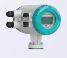
Features and Applications
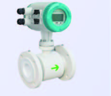
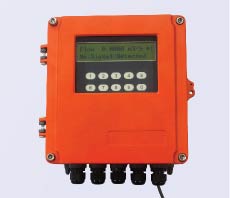
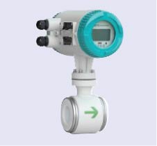
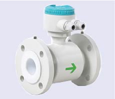
P-FM910-E series smart electromagnetic flow meter design using latest technology is made for high performance and accuracy. It is capable of measuring normal or reverse flow measurement, positive or negative totalize flow, etc also for conductive liquids such as water, sewage, acid, alkali and salt as well as mixture of liquid and solid.
Technical Specifications
| Power Supply: | 240 VAC 50Hz or 24VDC |
|---|---|
| Power Consumption: | ≤ 20W |
| LCD Display with Push Buttons: | LCD with backlight displays percentage of flow, instantaneous flow and total flow, and alarm status. |
| Totalizer: | It’s used for calculating the accumulative total for forward and reverse flow. |
| Output Signal: | 4-20mA: Load Resistance 0 ~ 750ohms, 0-10mA: Load Resistance 0~1.5 Kohms for Flow Rate. |
| Frequency Output: | Forward and reverse flow output with frequency range set between 1 ~ 5000Hz. The external voltage must be lower than 35V and the maximum output current is 250mA when the transistor is turned on. |
| Alarm Output: | Two outputs from the collectors of photoelectric isolate transistors are for alarm signals. The external voltage must be lower than 35V and the max output current is 250mA when the transistor is turned on. Alarms are set for empty pipe, excitation circuit failure, flow limit exceeded, etc. |
| Pulse Output: | For output in forward and reverse flow measurement, upper frequency of pulse output can be up to 5000 Hz. The flow per pulse is from 0.0001 to 1.0m3/pulse. The width of the pulse can be set to 20ms or square waveform automatically. The collector of transistor with photoelectric isolation is an open circuit. The external voltage must be lower than 35V and maximum of output current is 250mA when the transistor is turned on. |
| Accuracy: | ±0.5% of reading, ±0.3% or 0.2% available |
| Damping Time: | Adjustable between 0 and 100% |
| Communication Interface: | RS-485 MODBUS RTU |
| Power Failure: | A fail-safe clock is designed in the flowmeter, which can save the power failure event for up 16 records (F1F0). |
| Protection: | IP65/IP67 (dustproof and submersion for short time) |
| Pipe Sizes: | DN6 ~ DN1000 |
| Nominal Pressure: | 0.6 ~ 4.0 Mpa |
| Accuracy: | ±0.5% of reading, ±0.3% or 0.2% available |
| Liner Material: | PTFE, PFA, FEP, Neoprene, Polyurethane, etc. |
| Electrode Material: | SUS316L, Hastelloy-B, Hastelloy-C, Titanium, Tantalum, Platinum-iridium, Stainless steel covered with tungsten |
| Medium Temperature:
Remote Type: |
Integral Type: -100C ~ + 800C
Neoprene and Polyurethane Liner – -100C ~ +800C |
| Ambient Temperature: | -250C ~ + 600C |
| Ambient Humidity: | 5 ~ 100% RH |
| Medium Conductivity: | ≥ 5 S/cm |
| Measuring Range: | 1500:1, flow velocity ≤ 10 m/s |
Measuring Principle
The measurement of flow rate of the electromagnetic flowmeter is based on Faraday’s law of electromagnetic induction.
When the conductive liquid moves within the magnetic field, voltage is induced in it, whose magnitude is proportional to the velocity of the conductor. The equation is as below;
- E=KBVD
- K: Coefficient of the flowmeter
- B: Pulsed magnetic flux density
- V: Average velocity of the media
- D: Inner diameter of the measuring pipe
Dimensions
| Nominal Pressure | Meter Size and Dimensions | |||||||
| PN10 | inch | mm | L | D | inch | mm | L | D |
| ½ | 15 | 200 | 89 | 8 | 200 | 350 | 343 | |
| 8/4 | 20 | 200 | 98 | 10 | 250 | 400 | 406 | |
| 1 | 25 | 200 | 108 | 12 | 300 | 400 | 482.6 | |
| 1-1/4 | 32 | 200 | 117 | 14 | 350 | 400 | 533 | |
| 1-1/2 | 40 | 200 | 127 | 16 | 400 | 450 | 597 | |
| 2 | 50 | 200 | 152 | 20 | 500 | 450 | 699 | |
| 2-1/2 | 65 | 200 | 178 | 24 | 600 | 600 | 813 | |
| 3 | 80 | 250 | 190 | 30 | 750 | 750 | 985 | |
| 4 | 100 | 250 | 229 | 36 | 900 | 900 | 1170 | |
| 5 | 125 | 250 | 254 | 40 | 1000 | 1000 | 1289 | |
| 6 | 150 | 300 | 279 | |||||
Selection Principles
The medium being measured must be conductive liquid whose electrical conductivity should be more than 5 μ S/cm. The medium shouldn’t contain too much magnetic matter or air bubble. Pressure rating, lining material, electrode material and the configuration type should be selected according to the medium’s temperature, corrosiveness, abrasiveness, etc. Also, the following points should be considered;
-
- Normally, the size of the meter should be the same as the pipe size.
- Recommended flow velocity is 1 ~ 3 m/s if the medium contains particles. If the actual flow velocity is too big, the select higher size to reduce the flow velocity and the abrasion onto the pipe wall.
- Recommended flow velocity is 2 ~ 5 m/s if there is deposit in the pipe. Select lower meter size to increase the flow velocity and reduce the negative influence on the accuracy by the deposit if the actual flow velocity is too low.
- If the flow velocity is too small and a high accuracy is required, then smaller meter size is recommended to increase the flow velocity and ensure the accuracy.
Velocity-Flow Rate Table
| Pipe Size | Min. Flow Rate
(0~0.5 m/s) |
Max. Flow Rate
(0~10 m/s) |
|
| mm | Inch | l/min, m3/h | l/min, m3/h |
| 10 | 3/8 | 0 ~ 2 l/min | 0 ~ 40 l/min |
| 15 | 1/2 | 0 ~ 5 l/min | 0 ~ 100 l/min |
| 20 | ¾ | 0 ~ 7.5 l/min | 0 ~ 150 l/min |
| 25 | 1 | 0 ~ 10 l/min | 0 ~ 200 l/min |
| 32 | 1.25 | 0 ~ 20 l/min | 0 ~ 400 l/min |
| 40 | 1.5 | 0 ~ 30 l/min | 0 ~ 600 l/min |
| 50 | 2 | 0 ~ 3 m3/h | 0 ~ 60 m3/h |
| 65 | 2.5 | 0 ~ 6 m3/h | 0 ~ 120 m3/h |
| 80 | 3 | 0 ~ 9 m3/h | 0 ~ 180 m3/h |
| 100 | 4 | 0 ~ 12 m3/h | 0 ~ 240 m3/h |
| 125 | 5 | 0 ~ 21 m3/h | 0 ~ 420 m3/h |
| 150 | 6 | 0 ~ 30 m3/h | 0 ~ 600 m3/h |
| 200 | 8 | 0 ~ 54 m3/h | 0 ~ 1080 m3/h |
| 250 | 10 | 0 ~ 90 m3/h | 0 ~ 1800 m3/h |
| 300 | 12 | 0 ~ 120 m3/h | 0 ~ 2400 m3/h |
| 350 | 14 | 0 ~ 165 m3/h | 0 ~ 3300 m3/h |
| 400 | 16 | 0 ~ 225 m3/h | 0 ~ 4500 m3/h |
| 450 | 18 | 0 ~ 300 m3/h | 0 ~ 6000 m3/h |
| 500 | 20 | 0 ~ 330 m3/h | 0 ~ 6600 m3/h |
| 600 | 24 | 0 ~ 480 m3/h | 0 ~ 9600 m3/h |
| 700 | 28 | 0 ~ 660 m3/h | 0 ~ 13200 m3/h |
| 800 | 32 | 0 ~ 900 m3/h | 0 ~ 18000 m3/h |
| 800 | 36 | 0 ~ 1200 m3/h | 0 ~ 24000 m3/h |
| 1000 | 40 | 0 ~ 1350 m3/h | 0 ~ 27000 m3/h |


